TT bike and Di2 Customizing
I received 'a bike' for 'someone' and I knew I could get a bit more speed out of it.
It is going to be a training-possibly-racing bike and I set out to fix it up. I knew I wanted to keep the components as original as possible to keep with current sponsors. I had to be "visually" modified as little as possible to make it look normal to the untrained eye.
Before:


After:It is going to be a training-possibly-racing bike and I set out to fix it up. I knew I wanted to keep the components as original as possible to keep with current sponsors. I had to be "visually" modified as little as possible to make it look normal to the untrained eye.
Before:
Rat's Nest
Not Aero.

New Front View.
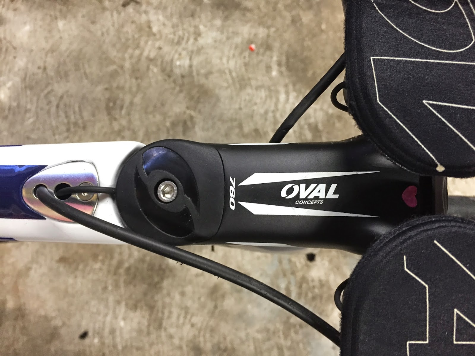
Top View of stem
Electronic wire enters back of top cap. Rear brake housing is hidden from wind by the basebar.

Underneath View of stem
Cables enter stem between faceplate and stem body. Best I could do to hide them other than drilling the center out of the base bar and some other hole-making.

Rider's POV


Surgery. Super secret tip. A plastic straw just fits over the E-Tube wires and allows them to slide through holes that are not smooth nor very big.


What is not seen currently:
There is one internal junction box in the stem and one in the left extension. With all the shifters (4 wires) plus the wire coming from the BB area, that makes 5 wires. That's why there is a second JC41 box because each one connects only 4 wires at a time. The 5 port B box could not be inside the stem because I wanted it exposed for battery check and adjustment features. I've heard you can run two B boxes so I could have used a dummy 5 port in the stem for the 5 connections and then the one under the BB for adjustments.

Did you test your gains?
ReplyDeleteThis comment has been removed by the author.
DeleteBeen looking for someone whose done a job like this on a Norcom for ages, this is v slick.
ReplyDeleteCan you explain the front-end junction box setup though? It looks like 4 wires are entering the stem and then one comes out and goes into the frame. How do you do this with only a single junction box inside the stem? Wouldn't this require 2 (which don't both fit)?
You are right. I don't remember what I did there to make that work! I have since updated the layout that uses one di2 wire inline (and heatshrinked together with) the rear brake housing.
Delete